Mechanical
OBSTACLE AVOIDANCE DRONE
Baskaran K

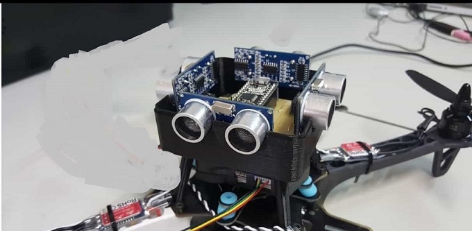
Recent times all the drones are coming along with the obstacle avoidance technology where it can able to sense any kind of obstacle by using the sensors. This technology protects the drone from crashing.
Read more..
Sensors detects the obstacle and sends the signal to the microcontroller, the signal is processed by the controller and sends the processed output signal to the flight controller, again flight controller sends the signal to the ESCs which is connected to the motor so the drone will be saved from hitting any obstruction.
You can fix the sensors in any direction that you want to. Depending upon the sensor that you use the obstacle distance will be changed.
Project Description:
- FRAME: Frame size can be changed depending upon the payload that you want. All the electrical and electronics will be placed over on the frame.
- FLIGHT CONTROLLER: The flight controller(autopilot) will be fixed over the frame which controls all the motors automatically when pre-programmed by the software.
- MICROCONTROLLER: Arduino board.
- SENSORS: Ultrasonic sensor or stereo camera or IR sensor. etc.
- GPS MODULE: This unit will help you to follow the waypoint which was pre-programmed in the software.
- POWER MODULE: Power module is used to power the flight controller board where it also helps to trigger the RTL function internally when battery level gets low.
- ESC: Electronic Speed Controller used for controlling the speed of the BLDC motor.
- BLDC MOTOR: Here you can use BLDC motor for producing thrust which will help the drone to fly by overcoming the drag.
- PROPELLER: It is a device which converts the rotational motion into the thrust. Propeller is made up of airfoil design which will cause the pressure difference due to that propeller will move upward direction along with the drone.
- BATTERY: You can use lipo battery as a power unit. Battery size will be changed according to the drone size. This type of battery gives you high energy with less weight.
- TRANSMITTER AND RECEIVER: 2.4GHZ TX and RX. It should have minimum 5 channel
-
POWER DISTRIBUTION BOARD: It will distribute the battery voltage to all the ESCs equally
Latest projects on Mechanical
Want to develop practical skills on Mechanical? Checkout our latest projects and start learning for free
Project Implementation:
- Fix all the parts in the frame properly. The flight controller should be fixed properly into the center part of the frame which helps you get more stability.
- Sensor should be fixed properly to any side that you want to detect obstacle
- Connect the arduino board to the arduino software and upload the programming logic on to the board
- Connect the battery to the power module and open up your mission planner which you have already downloaded
- Install the stable firmware to the flight controller board
- Now do all the mandatory calibration and the flight mode that you want to fly in your transmitter in the radio calibration setup
- Do auto-tune for more stability where you don't need to give PID values manually
- Now you can go for test flying
Software requirements:
- Mission planner or Q-Ground control or Tower.
 Did you know
Skyfi Labs helps students learn practical skills by building real-world projects.
You can enrol with friends and receive kits at your doorstep
You can learn from experts, build working projects, showcase skills to the world and grab the best jobs.
Get started today!
Kit required to develop OBSTACLE AVOIDANCE DRONE:
Technologies you will learn by working on OBSTACLE AVOIDANCE DRONE:
OBSTACLE AVOIDANCE DRONE
Skyfi Labs
•
Published:
2018-05-07 •
Last Updated:
2022-05-20
 Looking to build projects on Mechanical?:
 Did you know